
Excuse my language....but those look f**king dope! – Satisfied Customer
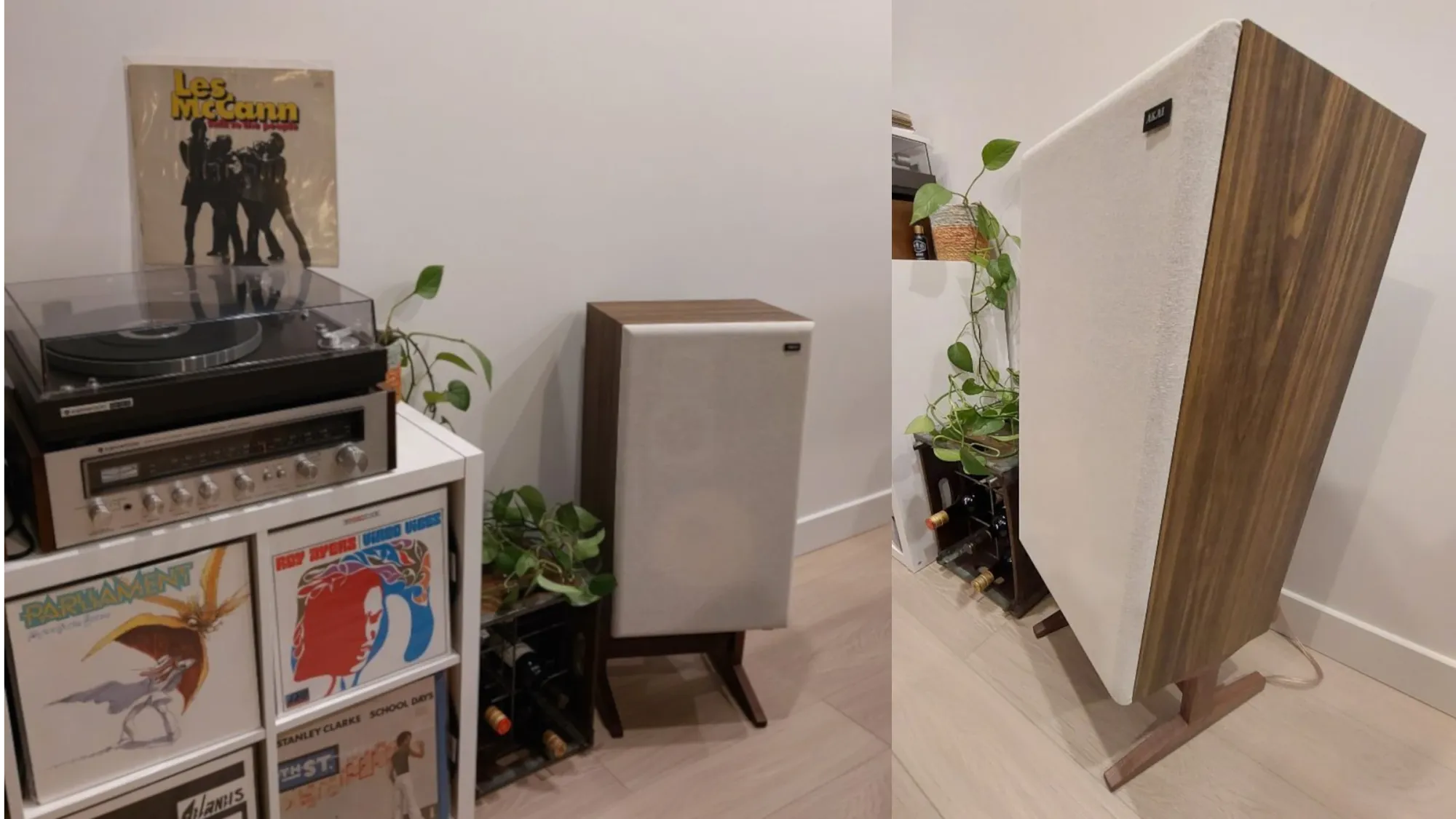
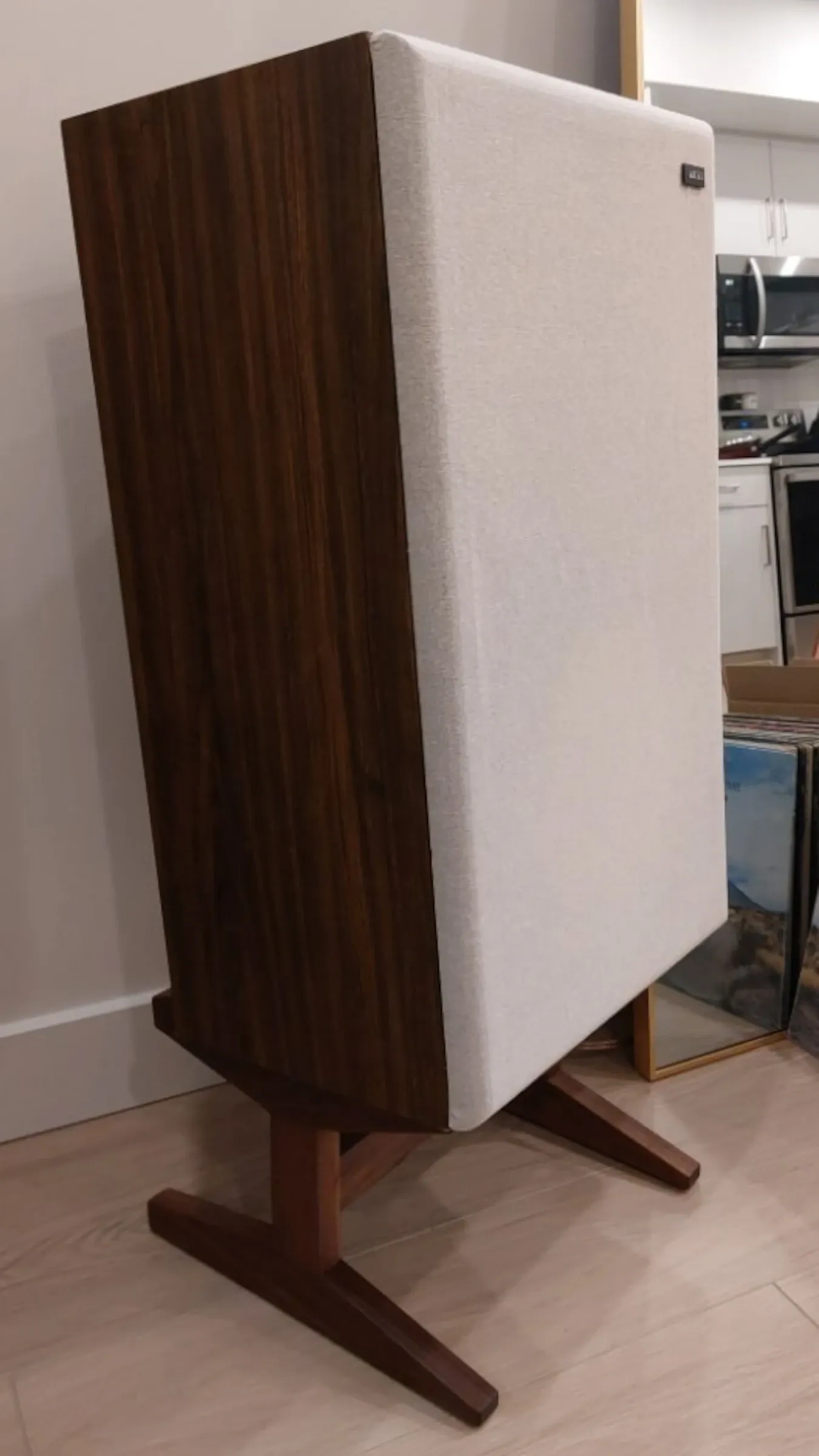
I recently received a commission to build a pair of stands for a set of floor speakers. The customer wanted to raise the speakers roughly 9" and tilt them back to improve projection. The speakers have a faux-walnut veneer so we decided to use solid walnut for the stands, so they would be reasonably close in colour.
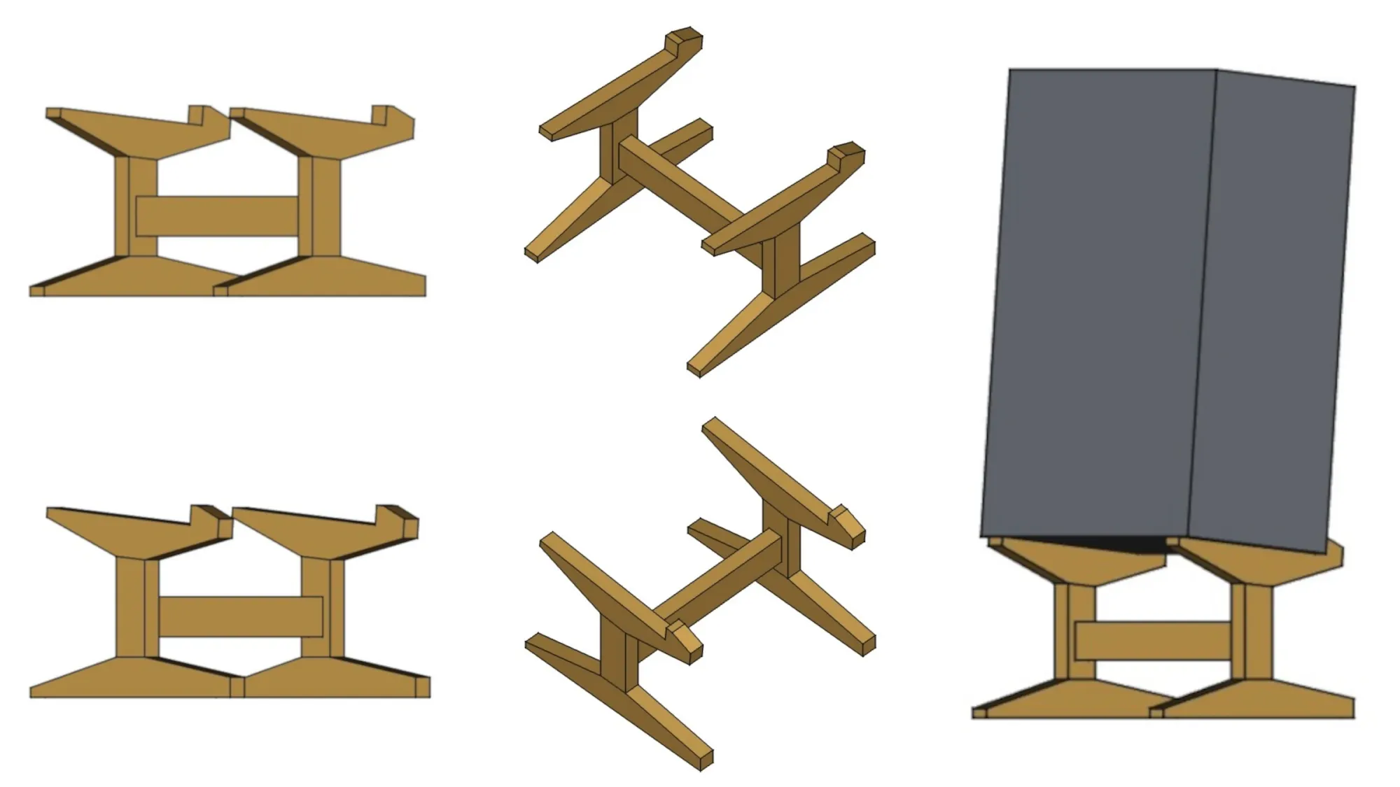
I started by building a parametric CAD model of the stands. I normally don't model my projects. I prefer to sketch things out in pencil on graph paper, and I generally only measure parts whose dimensions are critical to the success of the project. Everything else is marked and cut in reference to those critical parts. The benefit of having a model doesn't always justify the effort involved in creating it. However, I felt that I needed a model for this project, for a few reasons:
- The stands would tilt back and I didn't know what the ideal angle would be. Changing the angle would affect other dimensions, particularly the length of the joint between the leg and speaker support.
- I wanted to provide the customer with a simple rendering and to be able to respond quickly if they wanted changes.
Once the customer approved the rendering, I went shopping for lumber, milled it to the rough dimensions required by the designs, and stickered it for a few weeks to make sure it would be stable.
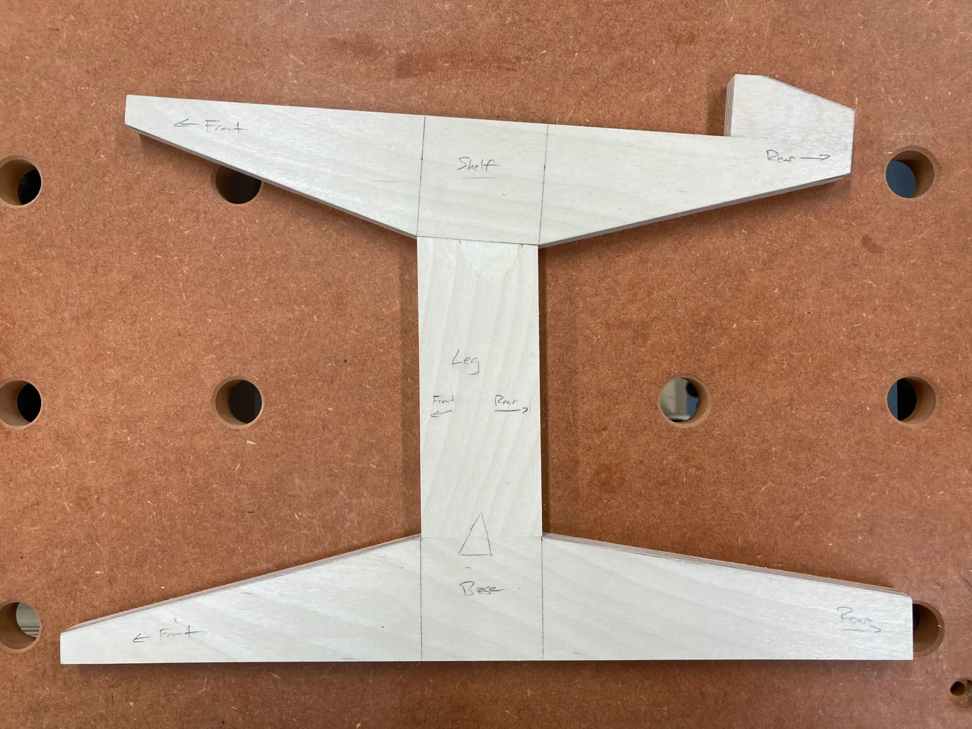
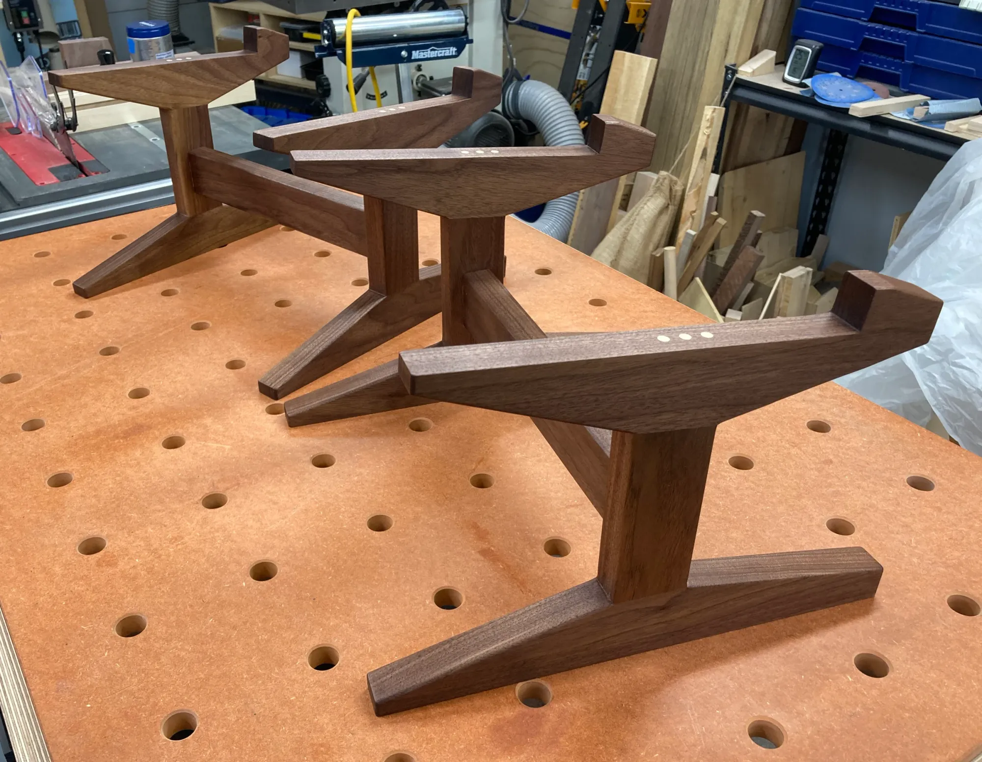
Each stand would have two leg assemblies, each consisting of three parts: the base, the leg and the speaker support. The leg assemblies had to be identical. Any deviation would prevent the stands from sitting properly on the floor, or prevent the speakers from sitting properly on the stands, or both. Either of these conditions could introduce vibration that would take away from the music. The best way to achieve the necessary consistency across all the parts would be to rout them to a template, so I made a templates for the three parts of the leg assembly from 12mm birch plywood. I traced the templates onto the lumber, cut the parts close to the lines on the bandsaw, and routed the parts to the templates. I also cut the cross brace for each stand on the table saw.
The parts would be assembled using three 1/4" dowels per joint. I marked precise center lines on the legs, continued the lines onto the bases and speaker supports, and used them to align my drilling jig. After drilling for the joints between the leg and base, and the leg and speaker support, I drilled another set of holes on the inside of each leg to attach the leg assembles to the cross brace. A dry fit of all the parts showed that dowel joinery could not guarantee that both speaker supports would end up with precisely the same tilt angle. It would be very easy for the leg assemblies to end up slightly out of plane with one another, so I needed a way to keep them aligned during glue-up. My solution was to use the dowel holes on the inside of each leg to keep the legs in the same position – leaving a bit of space between them so they wouldn't be glued together accidentally – and to clamp the bases and speaker supports between scraps of plywood to keep them coplanar.
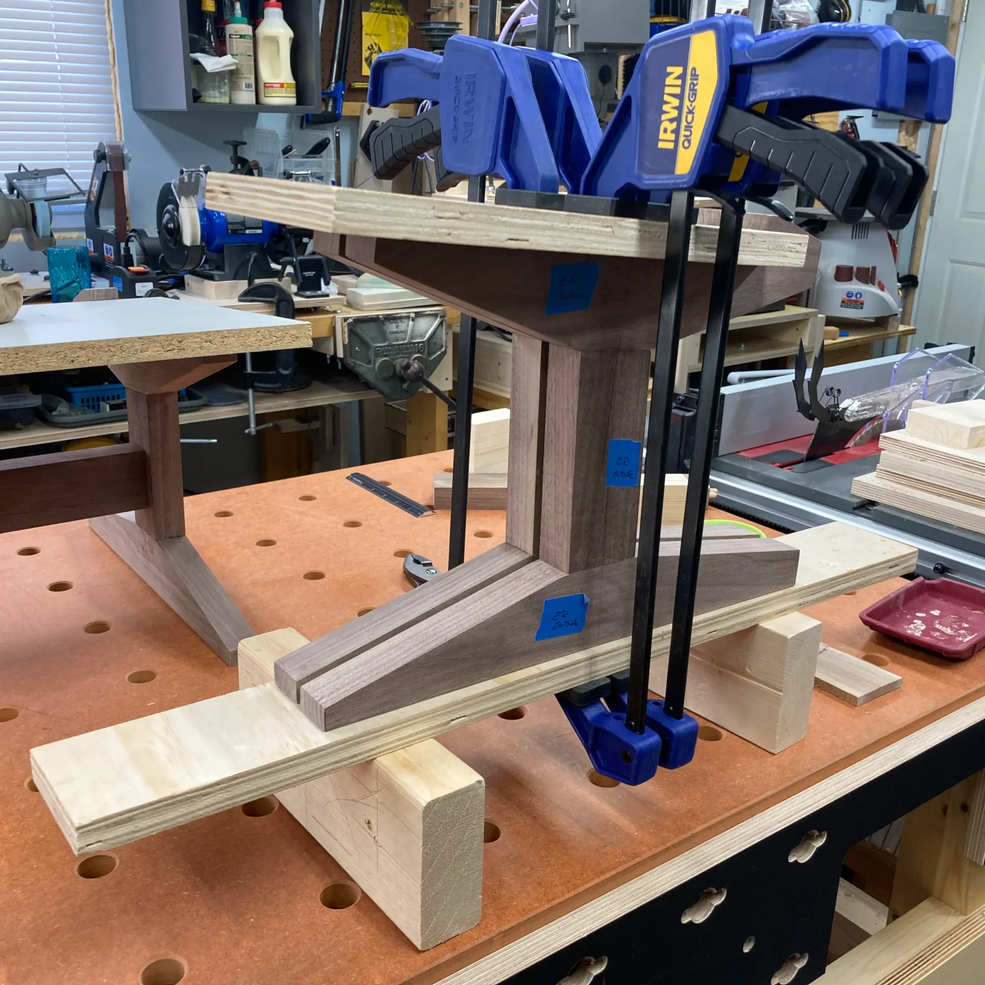
Next, I sanded the leg assemblies and cross braces, and routed roundovers around all the outside edges except where the stands would make contact with the speakers and the floor. I used a router to establish a consistent 1/8" radius for the roundovers but sanded them out by hand for a less mechanical look. The last step of assembly involved glueing the legs to the cross braces. I clamped them together lightly and put a five pound weight on top of each assembly to keep the legs planted to the bench while the glue dried. The result is a pair of stands that sit perfectly flat.
I finished the stands with Osmo Polyx hard wax oil in a satin sheen, which is my go-to finish for most things, but especially for walnut.
Overall, I'm very happy with how this project turned out. My customer's feedback has been overwhelmingly positive, not only with regard to the stands' appearance and basic functionality, but also with regard to the improvement they've made to how his speakers sound. That wasn't something we could plan for in advance, but decoupling the speakers from the floor and tilting them towards the listener should make a difference.
Thank you for reading!
If you found this post helpful, please consider supporting me by subscribing or sending a tip. It will help fund my work and writing.
- Click here to subscribe
- Click here to send a tip